Arduino -- The Beginning
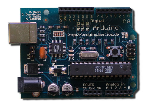
I think I'll post some stuff about the Arduino projects I'm working on.
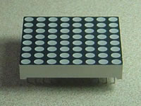
First thing, I'm trying to create a shield for an 8x8 monochrome LED matrix with variable brightness on each "pixel" LED. Such an animal might already exist, but I haven't found anyone doing exactly this.
A Start
I've already been playing with an 8x1 matrix and have a 4051 Analog Multiplexer (MUX) working beautifully. If I set the output level using analogOut (PWM), then update all the LED's (by scanning across them quickly) I can fade them up and down. However, if I attempt to directly manipulate the brightness of each LED in rapid succession it fails miserably.
PWM bites me in the butt
The reason for this is the way that the Arduino simulates "analog" voltages. The Arduino only has two choices for output voltage: 5v and Ground (0v). To "output" 2.5v, it pulses 5v to that pin half the time and 0v the other half (like a square wave) as fast as it can to supply and average of 2.5v. This is called Pulse Width Modulation (PWM). This works if the time that the target component has to react is significantly longer than the PWM cycle rate. (So it can react to the "average" voltage.) Since I'm cycling through the LED's as fast as the Arduino can loop, the PWM time isn't significantly faster than the refresh time, so the PWM "voltage" is basically undefined.
SIDE NOTE: the mystery of scanning displays
Most LED displays with a significant number of LEDs are not powered by lighting them up all at once, but rather by lighting each desired LED up in rapid sucession--much the same way that televisions and monitors scan the image down the screen rather than try to light up all the pixels at once. Persistence of vision and slow dimming rate of the pixels/LED's accomplish the rest by fooling your brain into thinking they are all lit up at once. Try video recording your alarm clock with the LED display, when you play it back, it'll flicker. This is why.
Screw PWM: A New Solution
So now my goal is to create an R/2R resistor ladder as a digital-to-analog converter to control voltages that way. (Using several, probably four, digital outs on the Arduino instead of the one PWM out.) I'm using an R/2R ladder because it turns out to be far easier to configure than the DAC chip (DAC08) I was trying to hook up a few nights ago.
Obligatory youtube link
Here's a video someone else made of an 8x8 and Arduino. Notice how may wires he used and that he's not even controlling all the LED's? That's why I'm using the 4015 MUX. I can control eight lights using only three lines (Binary 0-7 = 3 bits = 3 data lines.)
posted by Ric Johnson at
1:36 PM
0 Comments
Links to this post
![]()
